0086-13738869026emarketing@nide-group.com

2022-03-10
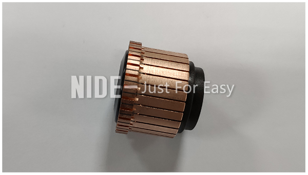
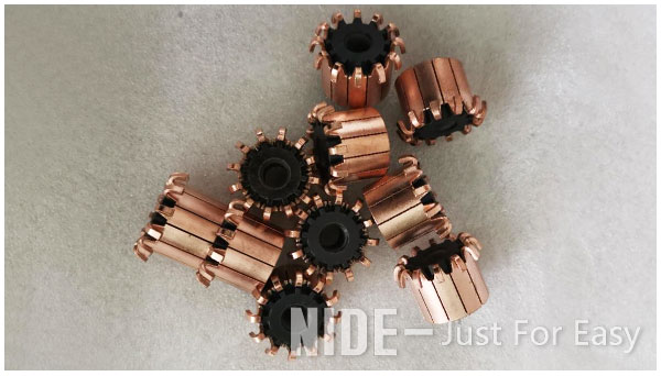
Commutator
The commutator itself is a split ring, typically made of copper, with each segment of the ring attached to each end of the armature coil. If the armature has multiple coils, the commutator will similarly have multiple segments—one for each end of each coil. Spring-loaded brushes sit on each side of the commutator and make contact with the commutator as it turns, supplying the commutator segments and the corresponding armature coils with voltage.
The basic purpose of commutation is to ensure that the torque acting on the armature is always in the same direction. The voltage generated in the armature is alternating in nature, and the commutator converts it to direct current. Simply put, the commutator turns the coils on and off to control which direction the electromagnetic fields are pointing. On one side of the coil, the electricity should always flow “away,” and on the other side, electricity should always flow “towards.” This ensures that the torque is always produced in the same direction. Otherwise, the coil would rotate 180 degrees one way, and then switch direction.
As the brushes pass over the gaps in the commutator, the supplied electrical charge switches commutator segments, which switches the electrical polarity of the armature coils. This switching of the polarity in the coils maintains the armature’s rotation in one direction. The voltage between brushes fluctuates in amplitude between zero and a maximum value, but always maintains the same polarity.
As mentioned earlier, the commutator is constructed in segments, which are insulated from each other. As the brushes pass from one segment to the other, there is an instant where the brushes contact both segments at the same time. This is referred to as the neutral plane, and at this point, the induced voltage is zero. Otherwise, the brushes would short the ends of the coil together and cause sparking due to high voltage.