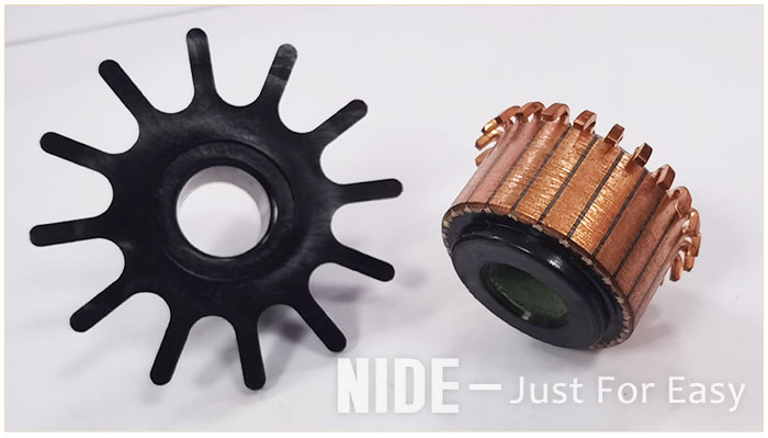
New technical solution for power tool commutator
The commutator is widely used in the automotive field, household motors, and electric tools. The basic structure of the commutator is: including the commutator copper sheets evenly distributed on the outer circumference of the commutator body, and the commutator body. Formed together, the commutating copper sheet is provided with a piece of foot which is implanted into the commutator body and firmly combined with the commutator body.
In order to strengthen the bonding strength between the commutator copper sheet and the commutator body, and improve the mechanical properties of the power tool commutator products, the most commonly used method is to improve the structure of the chip feet and set the reinforcement ring, and the improvement of the chip foot structure is the most ideal. The technical solution is to increase the size of the film feet. However, for power tool commutator products with small radial size and large number of commutation copper sheets, the size of its feet is strictly limited in both the circumferential and radial directions, and each adjacent commutation is strictly limited. The distance between the inner sides of the pins of the copper sheets will be very small. If the radial dimension of the pins is increased, the adjacent pins will easily touch when the commutating copper sheets and the commutator body are injected together. , resulting in a high rejection rate of commutator products after injection molding.
In view of the shortcomings of the existing technology, we provide a new commutator technical solution, which can improve the firmness of the combination between the commutator copper sheet and the commutator body, making a power tool commutator with higher product quality.
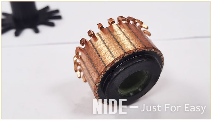
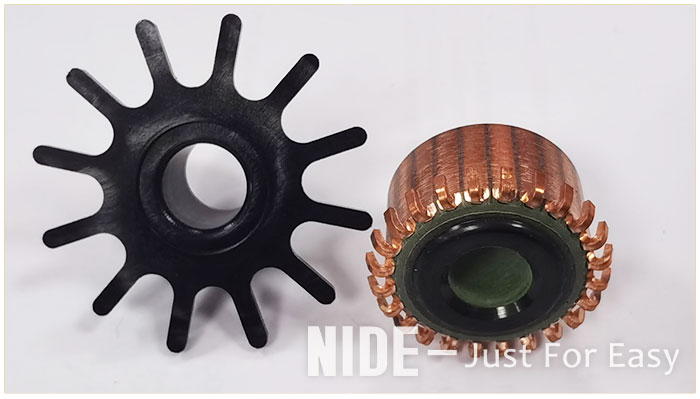
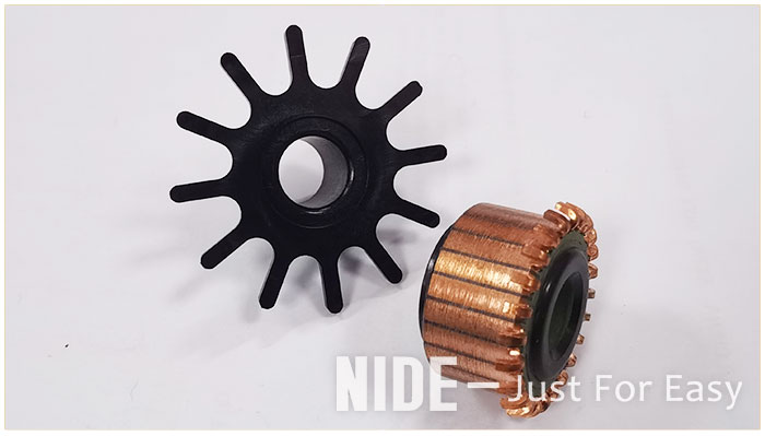
This is a special commutator for power tools, including a commutator body, and a commutator copper sheet is arranged around the commutator body. The top of the commutator body is provided with an insulating ring, the bottom of the insulating ring is provided with a flange ring, the flange ring is bent toward the top of the insulating ring to form an annular groove, and there are no less than six groups of gaps in the annular groove. Distributed bayonet group, the bayonet set includes a first card slot and a second card slot, the first card slot is located on the side wall of the annular groove, and the second card slot is located on the bottom wall of the annular groove. The commutation copper sheet is provided with a piece foot, and the piece foot is provided with a clamping foot arranged in an L-shaped longitudinal section. The clamping leg is clamped in the annular groove, and the end of the clamping leg is provided with a crack, which divides the clamping leg into a first leg and a second leg. The first leg is bent at 90° and embedded in the first card slot, and the second leg is embedded in the second card slot. The first card slot and the second card slot are arranged in a rectangular shape, and the inner walls of the first card slot and the second card slot are both provided with raised lines. The reversing copper sheet, the sheet pin and the clamping pin are set as a whole.
By adopting the above technical scheme of the power tool commutator, the clamping feet on the commutating copper piece are matched with the annular groove on the insulating ring, so that the structural strength of the commutating copper piece and the commutator body after installation can be improved. The feet 1 and 2 on the sheet feet are respectively embedded in the card slot 1 and the card slot 2, which can further improve the firmness of the connection between the commutating copper sheet and the insulating ring, thereby improving the commutator body and the commutating copper sheet. The bonding strength between them improves the mechanical properties of the product.